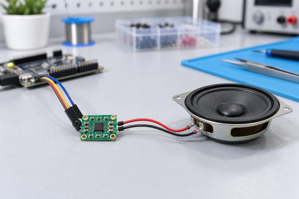
A MAX98357A I2S amplifier is a practical speaker-output option for ESP32 voice terminals, spoken prompts and compact audio devices. For a buyer, the risk is often hidden behind a familiar listing title: the quoted item may be a different IC variant, a different breakout revision or a board whose power claim uses conditions your product will never meet.
This guide turns those uncertainties into questions for the supplier and checks for the sample bench. The electrical facts come from Analog Devices; the RFQ and acceptance steps are a proposed purchasing workflow, not a claim that every supplier or batch has been tested.
What the MAX98357A I2S amplifier does
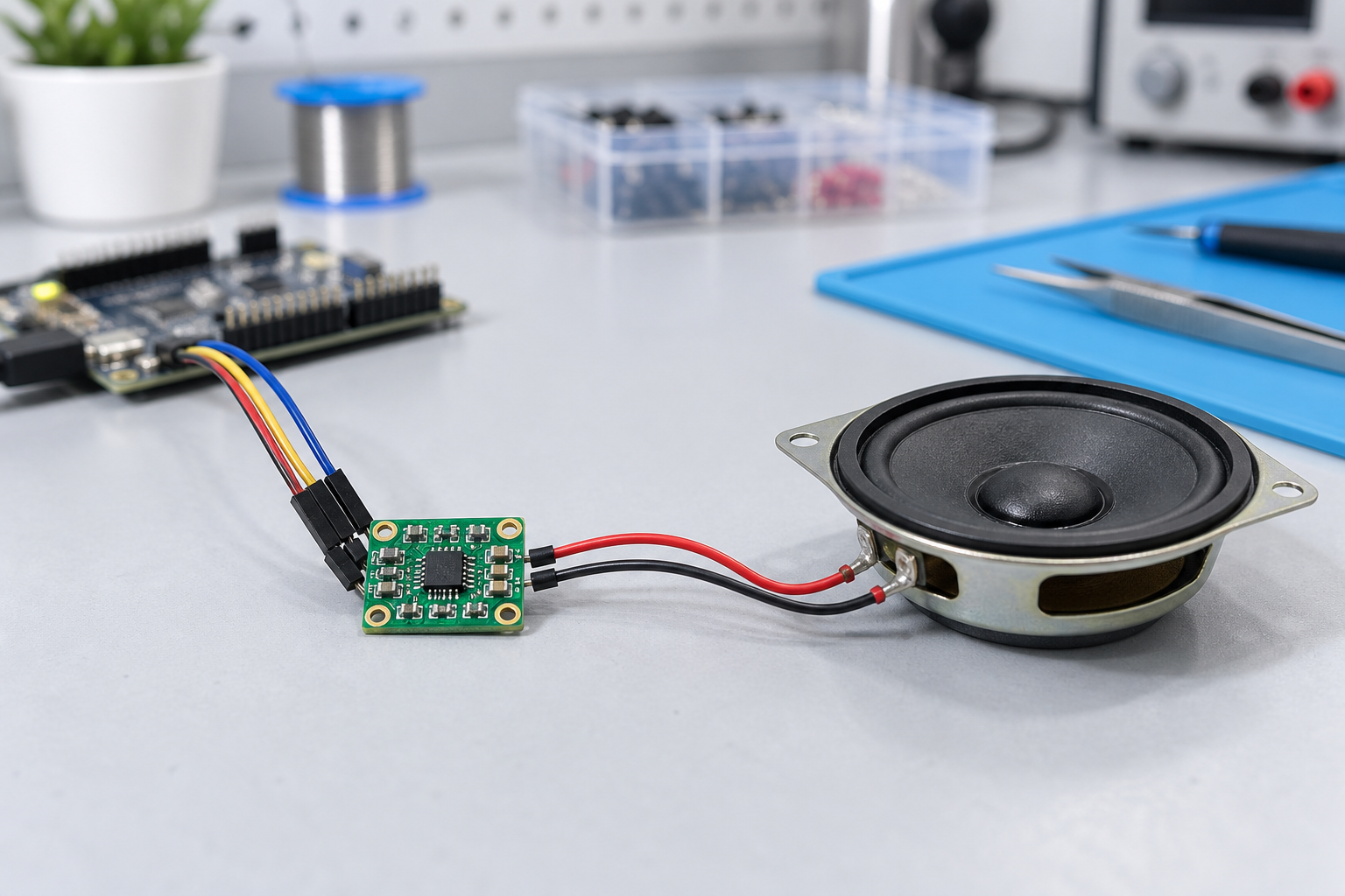
The MAX98357A is a mono digital-input Class D speaker amplifier. It accepts I2S audio; the related MAX98357B uses left-justified audio. The supply range is 2.5-5.5 V, and no separate MCLK signal is required. Analog Devices lists 3.2 W into 4 ohms at 5 V; usable output depends on the distortion target and operating conditions. Check the curves in the MAX98357A/MAX98357B datasheet before converting that headline into a product requirement.
This is an output amplifier, so it does not replace a microphone or an audio-input circuit. A voice device needs those functions specified separately. Our INMP441 microphone article covers the input side of that purchasing conversation.
Compare quotes using the same deliverable
| Quote field | What to confirm | Why it matters |
|---|---|---|
| IC or assembled module | Full ordering code or board manufacturer and revision | A bare IC price excludes the module’s assembly and connectors. |
| A or B variant | Required audio format | Similar names do not establish firmware compatibility. |
| Speaker and supply | Load impedance, rail voltage, target sound level | A power claim alone does not define audible performance. |
| Board configuration | Gain and channel-selection wiring, dimensions, pin order | Breakout revisions can alter integration requirements. |
| Delivery evidence | Lot identification, packaging, available quantity and delivery commitment | A catalogue entry is not a reserved production lot. |
Problem: a substitute powers up but gives silence or distorted audio
An amplifier can appear healthy while the host sends an incompatible audio format or the assembly selects the wrong channel. Replacing more boards without a controlled test only makes the fault harder to isolate.
Solution: request a reproducible audio test
Give engineering one approved board, a known PCM test file and a fixed firmware version. Record sample rate, sample width, slot arrangement and pin mapping. Begin at low level and compare a speech clip and test tone across the candidate modules. If one candidate fails, inspect the digital clocks and data before classifying the IC as defective. Confirm the A/B marking and the supplier’s schematic together.
Problem: the advertised wattage becomes the purchase specification
A small speaker may sound harsh well before a headline output rating is useful. The finished enclosure and its required listening distance determine whether the product is acceptable.
Solution: define the listening test and electrical conditions
Write down the supply voltage at the amplifier during playback, the chosen speaker, the enclosure and the maximum allowed volume setting. Agree a speech-intelligibility or distortion target with engineering. Ask for the conditions behind a supplier’s wattage figure, including load and distortion. Compare samples at those same conditions, and keep recordings or measurements with the approval record.
Problem: the device resets when speech and Wi-Fi run together
Audio peaks add a workload that a quiet demonstration may not exercise. A weak cable, connector or supply path can make an apparently good amplifier board look unreliable when installed beside a wireless controller.
Solution: test the complete power path
Play the loudest intended content while the controller performs its normal wireless work. Observe the supply at the amplifier and MCU, and record resets or audible interruptions. Use the production cable and power source. If the fault follows voltage droop, have engineering revise the regulator capacity, wiring or local decoupling before requesting replacement amplifier stock.
Problem: a repair treats the speaker output as ground referenced
The speaker connects across OUTP and OUTN. These are bridge outputs; neither terminal should be treated as ordinary ground. A familiar two-wire connector can hide this distinction.
Solution: document the output connection in the service procedure
Label the speaker harness clearly and require a suitable differential measurement method when inspecting the output. Do not attach a grounded oscilloscope clip to a speaker terminal. Before approving a repair module, engineering should verify output topology and wiring against the original design.
What to request before placing a production order
- Full IC ordering code and package, or an identifiable assembled-module revision.
- Schematic or connection drawing showing gain and channel-selection configuration.
- Sample units from the proposed supply route, with lot and packaging information.
- Written prohibition of unapproved IC, PCB or component substitutions.
- Agreed incoming test procedure, failure handling and delivery schedule.
Keep authenticity review separate from basic function. A board that produces sound does not prove component provenance. For a higher-consequence product, use a traceable supply channel and involve quality engineering in the inspection plan. Avoid inventing a universal burn-in duration or sample size; choose them according to the product and purchasing risk.
Buying takeaway
The useful comparison is an approved amplifier, speaker and power arrangement at an agreed sound level. That gives purchasing a clear specification and gives suppliers a fair acceptance target. Consult the manufacturer product page for current documentation, and send your quantity, board requirements and speaker details through our contact page for a sourcing review.
FAQ
Can MAX98357B replace MAX98357A?
Only after engineering approves the audio-format change and validates the assembly. The variants are not automatically interchangeable.
Will a 3.3 V supply deliver the quoted 3.2 W?
Do not assume so. The manufacturer’s headline figure uses 5 V and a 4-ohm load; evaluate the curves and your distortion requirement.
Can one module provide stereo speaker output?
The IC is mono. A stereo design needs a suitable two-channel arrangement with correctly selected channels.